Retro computing with a touch of modern and the home for all things, retroCombs (aka Steven Combs).
Disclosure Statement: When you click on links to various merchants on this site and make a purchase, this can result in this site earning a commission. Affiliate programs and affiliations include, but are not limited to Amazon, the eBay Partner Network, and/or others.

TEAR DOWN: Baofeng GT-3 Mark II
by Steven B. Combs, Ph.D.
I recently replaced the stock antenna on my Baofeng GT-3 Mark II with a Hypario® 771 dual band antenna. Reviews of the antenna suggest that I would receive an increase in receive and transmission range. Since I’m not licensed to transmit yet, I can only verify receive. It is an improvement.
However, it is not a good fit for the Baofeng GT-3 and somewhere down the line, the extra heft of the antenna along with several removals cause the antenna connector on the Baofeng to come loose and one day I even heard a small rattle in the hand-held unit. I decided to tear it down and determine what was going on.
Along the way I took pictures and thought I would share them with others who may have problems or who simply want to know what the inside of one of these little hand-held units looks like. I’ll share my findings and solutions to my problem at the end of the tear down pictures for those interested.
Tools
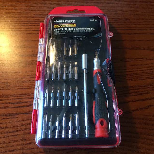
You will need a Torx and Philips screwdriver for this task. I use this 36-piece Husky set that has all necessary bits. Not sure where you can find these as this was a gift (Thanks Mark!). Apologize, but unsure as to the sizes you need. Any good precision set should have what you need.
Baofeng GT-3 Mark II tear down images
**WARNING: THIS WILL VOID YOUR WARRANTY!**Images appear first with descriptors underneath.
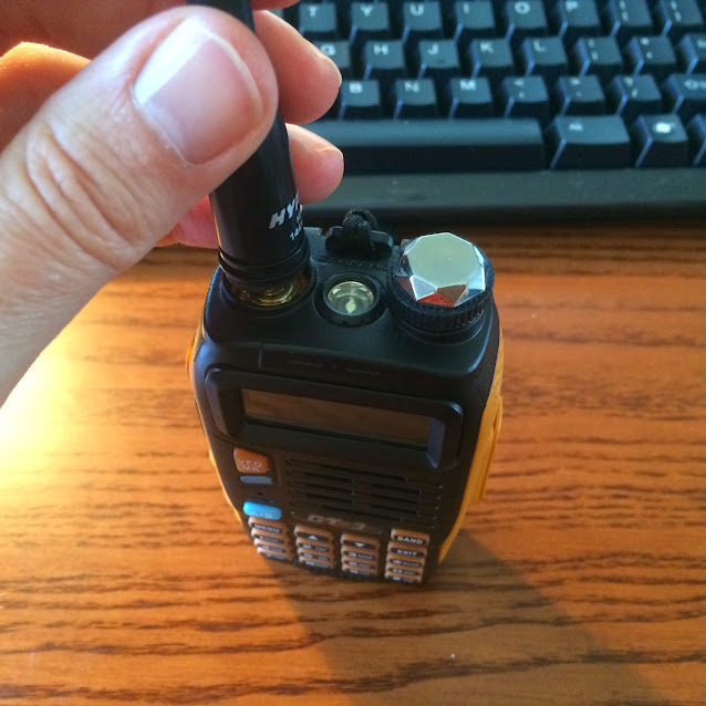 If installed, remove the antenna from the hand-held unit.
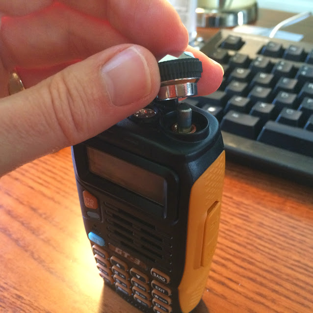 Pull the on/off/volume knob straight up. It will come off very easily.
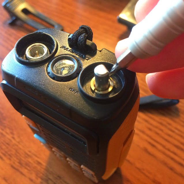
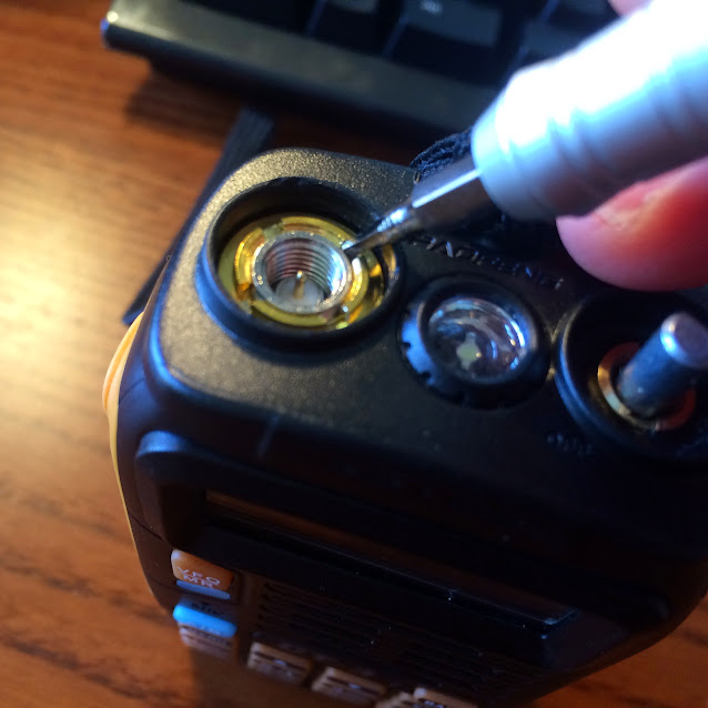 Remove the antenna connector ring. You will need a special tool or you can use a small screw driver. Be careful to not let the screwdriver slip and ding up the plastic. I found this came off very easily.
 Repeat the process above on the volume knob connector ring.
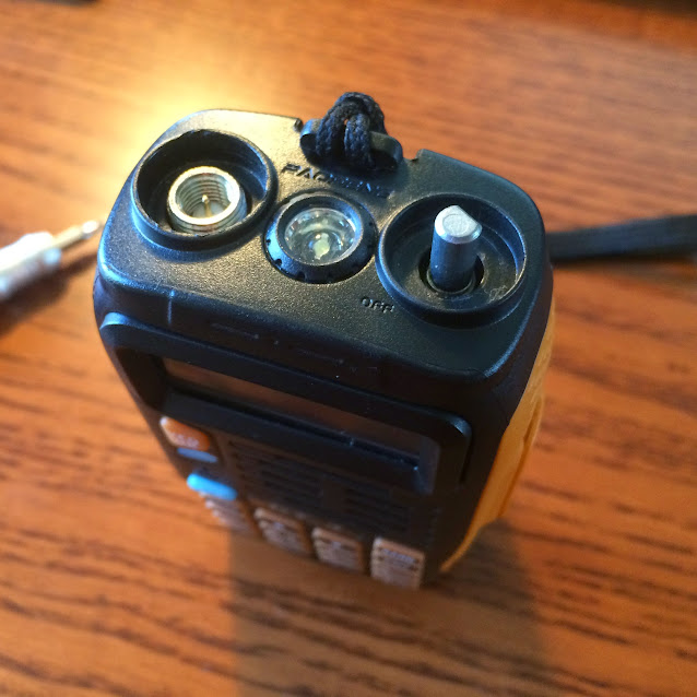 You should now have both connector rings removed as shown.
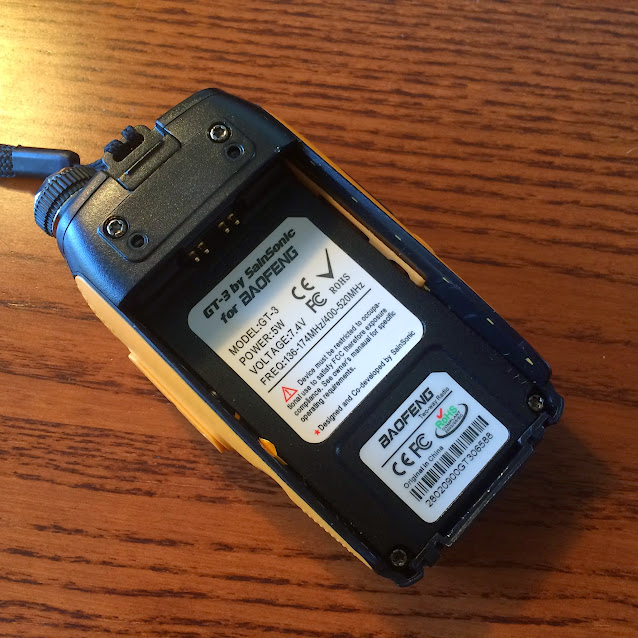
 On the back of the unit, remove the Philips screws that hold the optional spring loaded belt clip.
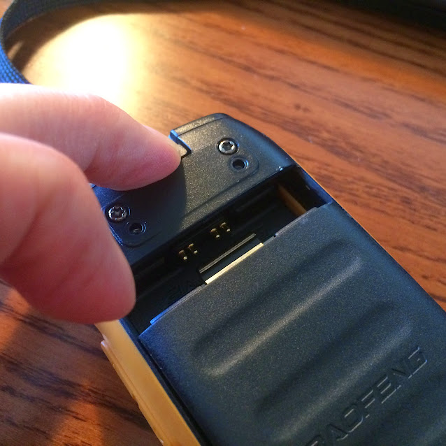 Remove the battery by pushing the battery release button at the top and then sliding the battery down.
 We are now ready to remove battery connector assembly and top back cover.
 Remove the two Torx screws that hold the battery connector assembly in place.
 With the two screws removed, we will now remove the upper battery connector assembly. Pay close attention to the next step.
 Swivel the assembly out as if there is a hinge attached. Do this VERY slowly. There is a sprint that will fly out if you remove the assembly too quickly.
 Sorry this image is blurry. See that spring in the middle of the image? Carefully remove it.
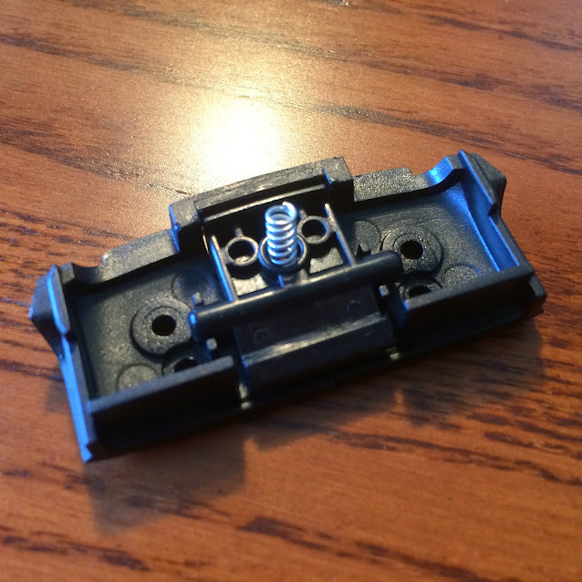 Turn the battery connector assembly cover over, set it aside, and place the small spring in the unit as shown. This will keep you from losing it.
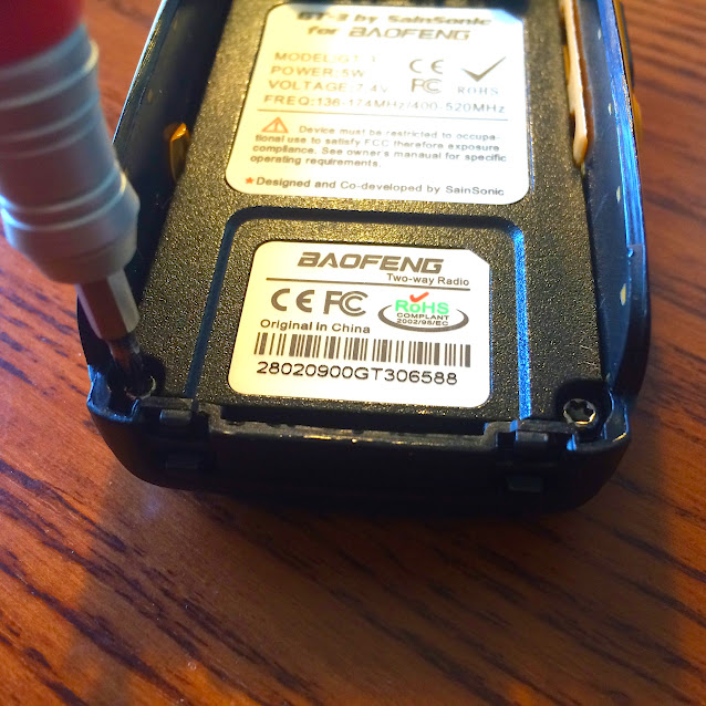 Break out the Torx screwdriver again and remove these two bottom screws.
 With the two screws removed, we will now lift the inside of the hand-held out of the outer molded assembly. As a reminder, this will void the warranty. There is a piece of adhesive that connects the PCB to the speaker that will come off. This reveals that the device was opened.
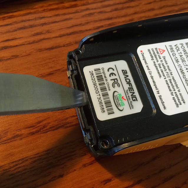 Use something to gently pry this PCB housing away from the molded assembly. I used a very dull knife. Probably not the best tool, but it was wide enough and readily available.
 Continue to slowly lift the bottom with your fingers until there is about a .5 inch gap. There’s about a 3 inch wire soldered between the speaker in the molded assembly and the housing you are removing. That’s all the slack you have.
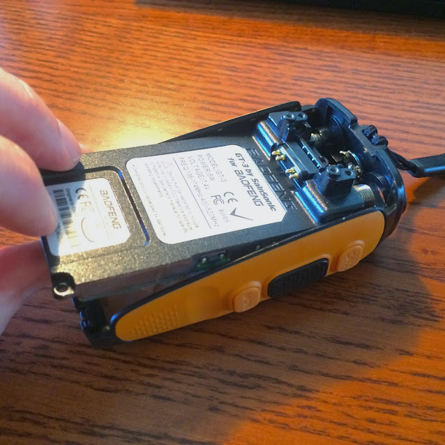 Slide the housing back slowly until the volume control, LED and antenna connector is free from their molded assembly openings.
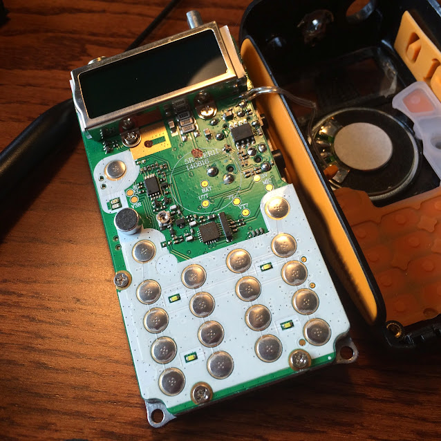 Now gently flip the assembly from the left to expose the PCB and be careful not to pull the speaker wire off. As mentioned earlier, during this process you will tear a piece of adhesive connecting the speaker and the PCB. It’s not needed, so completely remove it. You’ve already voided the warranty.
That’s all there is too it. That wasn’t hard; however, if you don’t have the steps outlined, it could be confusing and fraught with error. Hopefully, these steps will make it easier for someone else who needs/wants to open up their Baofeng GT-3.
To put the unit back together, simply reverse the process. I’ve assumed you can figure that part out. I’ve done this several times and its pretty easy.
Baofeng antenna solution
What was the initial antenna problem that led me to this tear down? It turns out that the rattle was from one of two screws that had previously held the antenna connector in place. It had fallen out and I also discovered that the other screw was stripped. I don’t believe this was my fault, but a there was a quick and easy solution to the problem.
My solution was to use some Gorilla Glue to ensure the connector would remain connected to the PCB forever. It worked nicely and there are no rattles and the connector is much more stable. It’s a true hack job that worked perfectly. I’ve been able to remove and connect antennas without any issues or loose connectors.
Even with my antenna problem, I think this little radio was a great $55 purchase and still a recommended radio for anyone new to amateur radio. I’ve learned a lot about this little radio and it has enhanced my understanding of radio concepts as I study for my Technician Class exam.