Retro computing with a touch of modern and the home for all things, retroCombs (aka Steven Combs).
Disclosure Statement: When you click on links to various merchants on this site and make a purchase, this can result in this site earning a commission. Affiliate programs and affiliations include, but are not limited to Amazon, the eBay Partner Network, and/or others.

retroCombs: The Tapuino Project - Build an Arduino powered Commodore Datasette clone for the Commodore Plus/4
by Steven B. Combs, Ph.D.
As part of my Commodore Plus/4 series, chapter three of the user’s manual includes a section on using a Commodore Datasette and a 1541 Diskette Drive. In a previous post, I assemble a replacement for the disk drive now it’s time to build a device I call the Tapuino.
What’s a Tapuino, you ask? It’s a cool Arduino-based replacement for the Commodore Datasette. For this project I use an Arduino, in this case the inexpensive Arduino Nano version with easy to source electronic components. You can learn all about the Tapuino on the Sweetlilmres 1337 beef: Building the Tapuino R2 blog post.
While this post focuses on the Tapuino for a Commodore Plus/4, this build will work with a C16 or other series Commodore computer. If you want to use the Tapuino with a VIC-20, C64, or C128, replace the 7 pin DIN connector with this C2N Power Adapter.
Sweetlilmre’s wrote his original blog post in 2015 and things have changed. His build uses veroboard to assemble and connect the Tapuino components. I use a breadboard. Later, I move my working Tapuino project to a “solderable” breadboard and create a custom 3D printed case.
This post, and the companion video, includes updates to build materials, layout, imagery, parts sourcing, and processes. Before you read this blog post, watch the video below. It shares my construction process and first use of the Tapuino.
YouTube Video
Title: Tapuino Project - Build an Arduino powered Commodore Datasette
In the video below, I breadboard and operate a Tapuino connected to a Commodore Plus/4:
Bill of Materials
The list below includes everything you need and the most inexpensive way I’ve found to source the project. Many pieces you have to purchase in multiples. This was not a problem for someone like me who has several projects on the bench at a time, but if you want the cheapest way to a Tapuino, purchase a kit or an assembled unit.
This site uses Amazon affiliate links. Thanks for supporting my content by starting your shopping using the links below:
- 1 - Arduino Nano V3 - This is the second nano I use in the video and not the first!
- 1 - 16x2 LCD Display with I2C backpack - The Tapuino can use other displays, but these are the most cost effective.
- 1 - SD Card module with built-in level conversion - Different from the unit Sweetlilmre specifies, but it works perfectly.
- 1 - Breadboard - Yes, this should work, unlike the one I had troubles with in the video.
- 1 - 430 Ohm resistor - Seriously, if you want to try this project and don’t have this resistor, for the cost of a SASE, I’ll send you one.
- 1 - Breadboard - One that works!
- 1 - 430 Ohm resistor - I have a bunch of these now.
- 4 - Momentary Switches with Color Caps - I didn’t use the color caps in this video, but may on my custom case.
- 1 - 4n25 Optocoupler - Same a resistor notes
- 1 - Spool of solid core breadboard wire: Multicolor will assist in wire tracking.
- 1 - Spool of solder - Just in case you are low.
- 1 - [7 Pin DIN plug connector - Plan accordingly if you e in the United States.S. because these take a while to get across the pond.
Makers or electronic hobbyist will have many of these items in stock (I did!). I did splurge with the purchase of the multi-color momentary switches and the all-in-one LCD screen with I2C backpack. I did not have a 4n25 optocoupler.
Tools
- Wire Stripper - Easy to use an a clear strip each time.
- Solder/Station - This is an inexpensive station that I recommend.
- Rosen Core Solder wire - In case you are running low.
Fritzing Time
The first step in my process was to use a regular breadboard to build the Tapuino using Sweetlilmre’s original Fritzing file below:
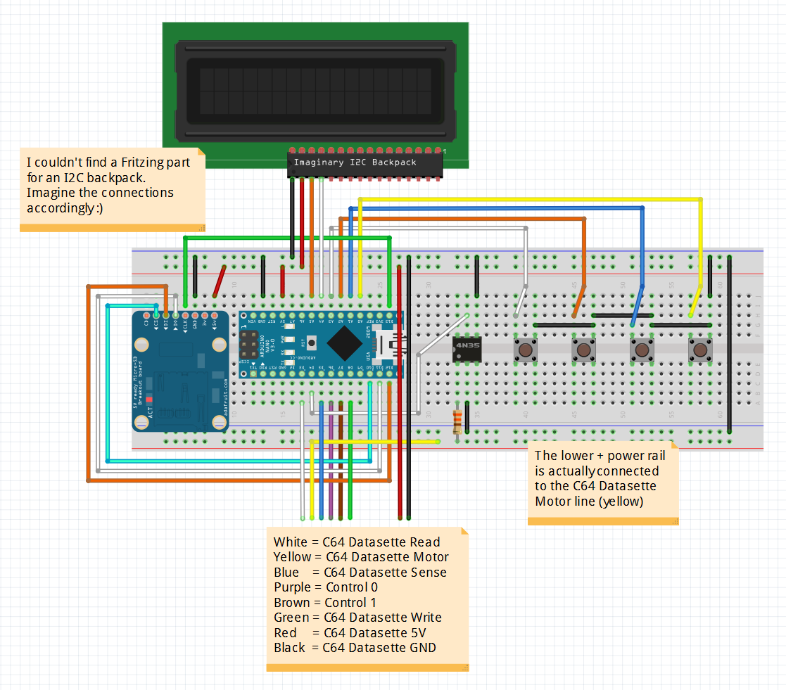
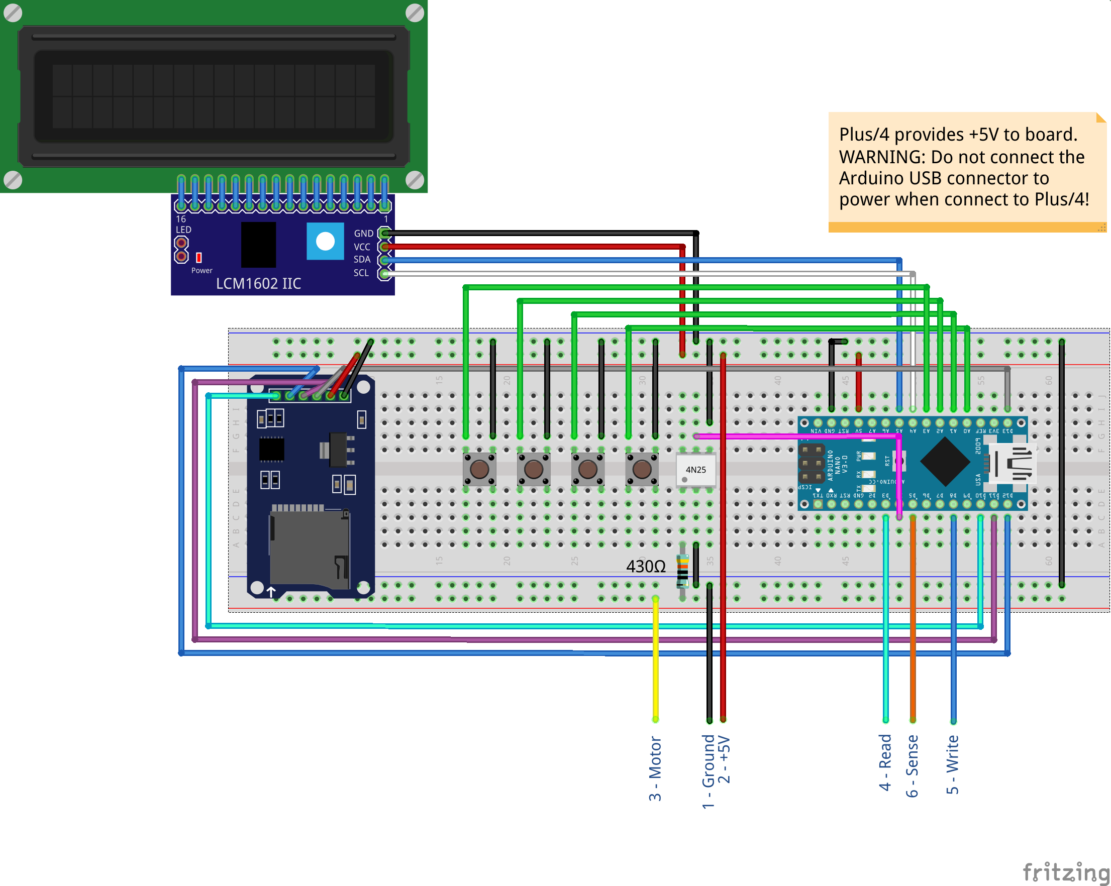
Afterward, I optimized the layout and part locations. There was little change since the original was efficient; however, I could locate updated Fritzing parts and took a different approach to labeling the cable connection. A Fritzing image of my layout is below.
Building the Tapuino
I demonstrate how to build the Tapuino in the video; however, below are additional thoughts and tips:
- While Fritzing allows me to document my build, the other advantage is that while laying out the Tapuino, I became more familiar with the build and how the components connect. This came in handy when troubleshooting.
-
I’d not used a 4n25 optocoupler; or opto-isolator (which is why it took me a few times to say it correctly in the video). Sweetlilmre’s site doesn’t explain what it does. Wikipedia says an optocoupler:
is an electronic component that transfers electrical signals between two isolated circuits by using light. Opto-isolators prevent high voltages from affecting the system receiving the signal. Here’s the data sheet if you’d like to learn more.
Next Up
One of the reason’s I used a solderable breadboard was to provide a permanent platform for the electronics. This way, I could design a 3D printed case. Leave your comments and questions below or in the comments under the YouTube video. I’ll do my best to answer them.
Join the Fun
Don’t miss the retro-computing fun. SUBSCRIBE to my YouTube channel and check out my other posts.
Help make this content better! Leave your comments, corrections, additions, and thoughts in the comments below. You can email me at retrocombs@icloud.com. Thanks for reading and if you are inclined, please let others know about the blog using the hashtag #retroCombs.
🕹️ retroCombs, OUT!