Retro computing with a touch of modern and the home for all things, retroCombs (aka Steven Combs).
Disclosure Statement: When you click on links to various merchants on this site and make a purchase, this can result in this site earning a commission. Affiliate programs and affiliations include, but are not limited to Amazon, the eBay Partner Network, and/or others.

Commodore Plus/4 User’s Manual Chapter 7 - Using Graphics and Color
by Steven B. Combs, Ph.D.
In this Commodore Plus/4 retroCombs episode and companion blog post, I cover Chapter 7, Using Graphics and Color, of the Commodore Plus/4 user’s manual. If you are eager to create images on your Commodore Plus/4, this is the chapter for you. Chapter 7 include information to PETSCII, colors, graphics modes, and other commands to create static images an animations. It’s a fun chapter and one that took quite a bit of time to prepare.
MEMBERSHIP: I now offer retroCombs memberships from $1 (PET level membership) to $20 (MEGA65 level membership) that include levels in between for all budgets (VIC-20, C64, Plus/4, and C128). If you’d like to support my content and get access to my Discord server along with other cool freebies, check out each level at https://www.buymeacoffee.com/retroCombs.
Table of Contents
- Series Information
- Companion Disk Image
- User’s Manual
- YouTube Video: retroCombs: Commodore Plus/4, Chapter 7 - Using Graphics and Color
- Video Errata
- Links Mentioned in this Episode:
- Key to Keys
- Introduction
- Graphics Characters
- Character Animation
- Controlling Colors
- High Resolution Graphics
- Points, Lines, and Labels
- The
CHARCommand - Squares, Circles, Polygons, and Painting
- The
PAINTCommand - Multi-Color Graphics
- Final Thoughts
- Join the Fun
Series Information
This episode is a small part of my larger Commodore Plus/4 series. You can read the entire series and view additional resources at:
</plus4>
Companion Disk Image
As I progress through the user’s manual, I enter and execute sample programs. The link below is to a .d81 image that contains every program from each episode. Like the series, the image is not complete.
retroCombs User’s Manual Disk Image - UPDATED AS OF: 2021-02-13
I use the following file name convention to make it easy to locate specific programs:
 Sample Program Name:
 02 RCOMBS SCROLL.PRG
02- The chapter numberRCOMBS SCROLL- my self assigned name for the BASIC program which will be immediately identifiable if you follow along.
User’s Manual
As part of my Commodore Plus/4 YouTube series, I work through each chapter of the Plus/4 manual. I’ve taken the time to scan each chapter so you can read and follow along. Use the link below to view chapter 7:
Chapter 7 - Using Graphics and Color
Below are the links for previous chapters covered:
- Front Matter
- Chapter 1 - Unpacking and Setting Up
- Chapter 2 - Using the Keyboard and the Screen
- Chapter 3 - Using Software
- Chapter 4 - Getting Started
- Chapter 5 - Numbers and Calculations
- Chapter 6 - Beginning BASIC Programming
YouTube Video: retroCombs: Commodore Plus/4, Chapter 7 - Using Graphics and Color
In the video below, I work through Chapter 6 of the user’s manual.
Video Errata
None as of 2021-02-18.
Links Mentioned in this Episode:
Below are the links I mention in the video. All Amazon links are affiliate links. Thanks for supporting the blog and the YouTube channel!
Key to Keys
Because the Commodore Plus/4 keyboard is so different from modern keyboards, I devised a modern key nomenclature to identify keystroke combinations as shown in the table below:
| Key | Description | Key | Description |
|---|---|---|---|
⇪ |
Caps Lock | F1 |
Function 1 |
[C=] |
Commodore | F2 |
Function 2 |
⌃ |
Control | F3 |
Function 3 |
⎋ |
Escape | F4 |
Function 4 |
⌂ |
Clear/Home | F5 |
Function 5 |
⌫ |
Insert Delete | F6 |
Function 6 |
⏎ |
Return | F7 |
Function 7 |
[R/S] |
Run/Stop | F8 |
Help |
⇧ |
Shift | ␣ |
Space |
↑ |
Cursor Up | ↓ |
Cursor Down |
→ |
Cursor Right | ← |
Cursor Left |
Introduction
- Thank you to all my viewers and the feedback.
- .d81 disk image is available here.
- Don’t forget to subscribe to the channel!
- Hope you’ve been keeping up with my retro-computing content like my latest project, the Combian pi/400. I love this Combian 64 and Raspberry Pi 400 mash-up. Other than my Dev Kit, It’s my new favorite modern emulation system. I plan to do more with it in the near future.
Graphics Characters
You will notice on the Plus/4 keyboard that not only does the keyboard allow for lower and upper case characters, but there’s a whole host of graphic characters available on each letter key, @, -, and *.
In upper-case mode, press and hold the ⇧ (right character) or C= (left character) key, followed by one of the keys listed above to place graphics characters on the screen. The characters are know as PETSCII (similar to ASCII on later computers) and each one can be displayed using the PRINT CHR$() command if you know the right address.
PETSCII (PET Standard Code of Information Interchange), known as CBM ASCII, is the character set used in Commodore Business Machines (CBM)’s 8-bit home computers, starting with the PET from 1977 and including the C16, C64, C116, C128[1], CBM-II, Plus/4, and VIC-20. - Wikipedia.
The character set expands when both shifted and unshifted modes are used. You can view a chart with PETSCII codes at https://sta.c64.org/cbm64pet.html.
The majority of PETSCII codes have been absorbed into ASCII; however, they can be difficult to find on modern keyboards. This makes a Commodore 8-bit computer much more adept at creating BASIC programs with animated characters.
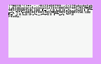
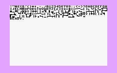
I wrote a BASIC program that will display PETSCII characters on the screen. DLOAD or type the program and then RUN the program. The screen will clear and the PETSCII characters will fill the top of the screen. and then tap the ⇧ + C= keys to cycle between upper and lower-case modes as shown in the images below the code. Right-side graphics characters are available in both upper and lower-case modes. Left-side characters include lines and angles used to draw tables and charts.
5 SCNCLR
10 FOR T = 33 TO 127 : PRINT CHR$(T); : NEXT T
20 FOR T = 160 TO 255 : PRINT CHR$(T); : NEXT T
💾 On Disk: 07 PETSCII
Community Addition
As my reader/viewership grows, so do the suggestions. I’m adding a new feature to the companion blog posts, community additions.
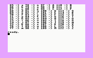
Frequent contributor to the comments and YouTube watcher, Jeffrey Phipps created a program to produce a formatted screen that displays upper and lower-case a-z (when in lowercase mode) PETSCII characters next to the CHR$ code. It’s a great addition.
10 SCNCLR
20 REM ** COUNT FOR THE FIRST 13 LETTERS
30 FOR X = 65 TO 77
40 C1 = X : REM COLUMN 1 - LOWER A-M
50 C2 = X + 13 : REM COLUMN 2 - LOWER N-Z
60 C3 = X + ASC(" ") : REM COLUMN 3 - UPPER A-M
70 C4 = X + 13 + ASC(" "):REM COLUMN 4 - UPPER N-Z
80 REM ** PRINT FOUR COLUMNS
90 PRINT C1;"-> ";CHR$(C1);
100 PRINT C2;"-> ";CHR$(C2);
110 PRINT C3;"-> ";CHR$(C3);
120 PRINT C4;"-> ";CHR$(C4)
130 NEXT X
💾 On Disk: 07 A to Z
Use combinations of the PETSCII characters to create lines, shapes, environments, characters, and even animations as we will cover next.
NOTE: When you “draw” images on the screen using PETSCII, holding down the
⇧or⇧-Lockwhile drawing and then following each line with⏎will not yield a syntax error. This is a great tip for prototyping screen designs.
Character Animation
You can use BASIC and PETSCII to create both images and animations. The three programs below create animations using traditional animation cels; one-by-one using the PRINT command.
PULSE BALL PROGRAM
Need a visual for an alarm, this program will perfectly and you can modify the speed of the pulse by changing the value of L.
10 ? "⌂●"
20 FOR L = 1 TO 100 " : REM CHANGE VALUE TO MODIFY SPEED
30 NEXT L
40 ? "⌂○"
50 FOR L = 1 TO 100 : REM SHOULD = L IN LINE 20
60 NEXT L
70 GOTO 10
💾 On Disk: 07 PULSE BALL
JUMPING JACK PROGRAM
It’s exercise time! This program will help you get your daily number of jumping jacks logged and you can make them as fast as you want!
5 SCNCLR
10 ? "⌂╲○╱"
20 ? " ▒ "
30 ? "╱ ╲"
40 FOR L = 1 TO 100 : NEXT L
50 ? "⌂ ○ "
60 ? "▔▒▔"
70 ? " ││"
80 FOR L = 1 TO 100 : NEXT L
90 GOTO 10
💾 On Disk: 07 JUMPING JACK
INCH WORM PROGRAM
The two examples above place animations on the screen that stay in the same location. In this program, our worm will inch its way along the top two lines of the screen and then stop.
5 FOR A = 0 TO 30 : REM CHANGE A BUT NOT > 36
10 SCNCLR
20 ? TAB(A)"╭╮╭╮"
30 ? TAB(A)"╯╰╯╰"
40 FOR L = 1 TO 100 : NEXT L
50 SCNCLR
60 ? TAB(A)"╮╭╮╭"
70 ? TAB(A)"╰╯╰╯"
80 FOR L = 1 TO 100 : NEXT L
90 NEXT A
💾 On Disk: 07 INCH WORM
MOVE BALL PROGRAM
We can make a simple animation by drawing an object, then erasing it, and then redrawing in the next adjacent space as shown in the code below. BASIC will draw a ●, then move back one space. The next line will overwrite the previous ● with a ␣ and then draw another ● to the right of the previous. It’s a simple animation that moves the ball from the top-left of the screen, line-by-line, until it reaches the bottom lower-right. Can you predict what happens next?
10 SCNCLR
20 ? " ●←";
30 FOR L = 1 TO 50 : NEXT L
40 GOTO 20
💾 On Disk: 07 MOVE ●
Controlling Colors
In our previous examples, all the characters have been black. We touched on changing colors back in Chapter 4. In this section we will spend more time learning how to modify not only individual character colors, but screen and border colors. Give is try with the examples below:
COLOR 4,3 will change the border color to red, kinda. More on this later. 4 is the item to color change, in this case the border, and 3 is the color.
COLOR 0,7 will change the background color to blue. 0 specifies a border color change with 7 once again representing the color.
COLOR 4,3,0 uses a third color value that sets color luminescence. Use this value to modify the “kinda” red and blue colors. Now the border will be “really” red.
The table below displays all COLOR command variables:
| Area | Color | Lum |
|---|---|---|
| 0 Background | 1 Black | 0 Darkest |
| 1 Character | 2 White | 1 |
| 2 Multi-color 1 | 3 Red | 2 |
| 3 Multi-color 2 | 5 Purple | 3 |
| 4 Border | 6 Green | 4 |
| 7 Blue | 5 | |
| 8 Yellow | 6 | |
| 9 Orange | 7 Brightest | |
| 10 Brown | ||
| 11 Yellow Green | ||
| 12 Pink | ||
| 13 Blue Green | ||
| 14 Light Blue | ||
| 15 Dark Blue | ||
| 16 Light Green |
NOTE: The Plus/4 can output 121 colors. Multi-color modes will be discussed in the Multi-Color Graphics section.
COLOR PALETTE PROGRAM
The program below will display all Commodore Plus/4 colors as shown in the image below:
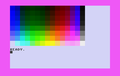
There was an error in the user’s manual code that I corrected. See REM statements within code for details.
5 SCNCLR
10 COLOR 0, 7, 7
20 FOR M = 0 TO 7
30 FOR N = 1 TO 2
40 FOR L = 1 TO 15 : REM CHANGE FROM 16 IN MANUAL
50 ? "[RVS ON]"; REM ⌃ + 9 FOR [RVS ON]
60 READ A
70 COLOR 1, A, M
80 ? "  ";
90 NEXT L
100 ?
110 RESTORE : REM MOVES DATA POINTER BACK TO START OF DATA LIST
120 NEXT N, M
130 COLOR 1, 2, 4
200 DATA 7, 14, 4, 13, 6, 16, 11, 8, 10, 9, 3, 12, 5, 15, 2, 1
💾 On Disk: 07 COLOR PALETTE
NOTE: I failed to talk about the
RESTOREcommand in the video. TheRESTOREcommand in line 110 is used along with theDATAcommand in line 200. As the program moves through the list of data, theRESTOREcommand will reset the point back to the very first data value, which is7in this example.
High Resolution Graphics
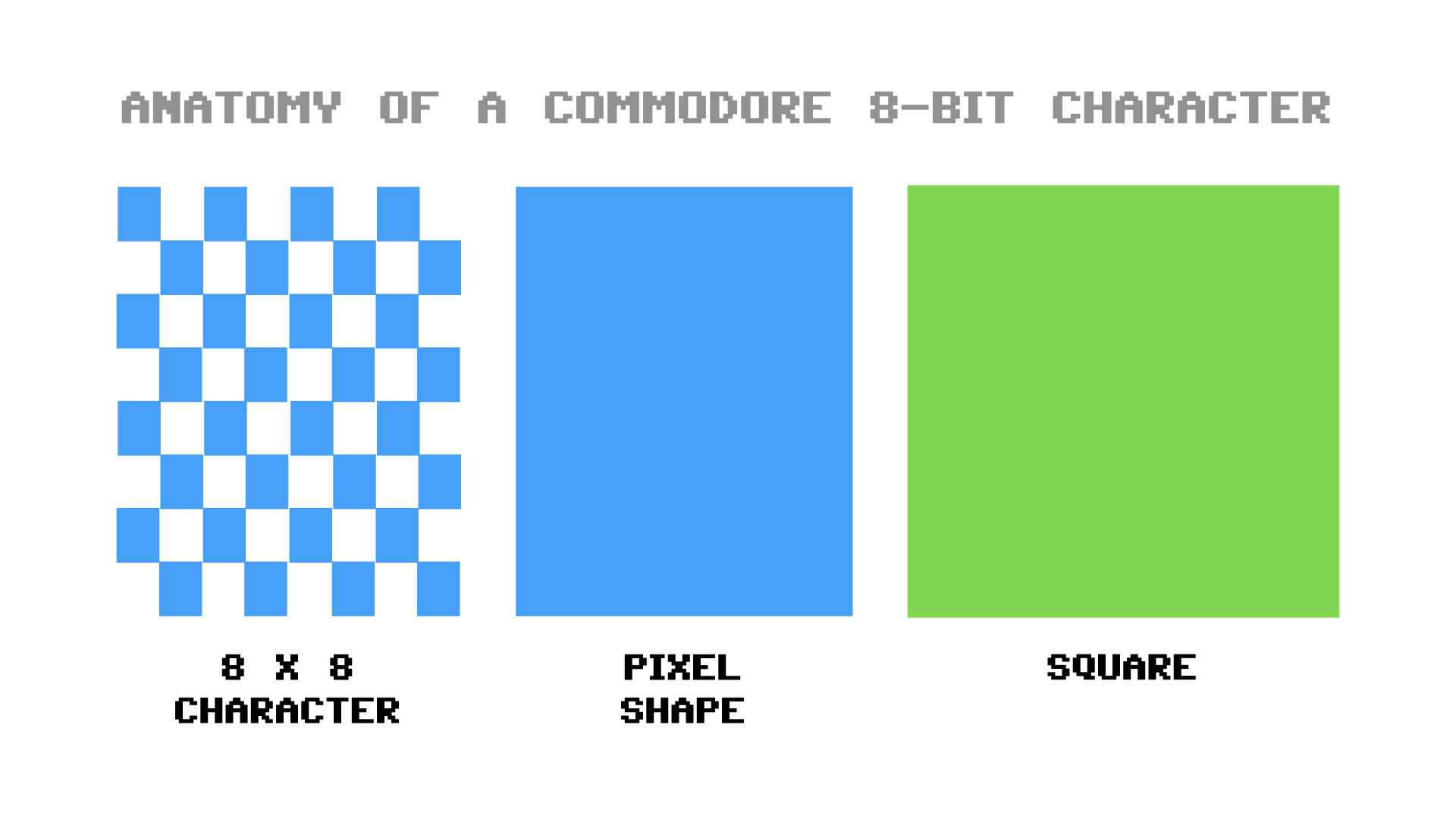
The Plus/4 screen contains 25 rows of 40 characters each for a total of 1000 character positions (25 x 40 = 1000). Each character is described by a grid of 8 x 8 pixels, or 64 pixels. Therefore, the full-screen resolution of a Plus/4 screen is 320, 200 and 64,000 pixels. So far, we’ve controlled each 8 x 8 grid only. In this section we will break that grid into the large screen and control all pixels individual to access “high resolutions graphics mode.”
While you may be thinking “cool, now I can use a single color for each pixel”, here’s the caveat. The Plus/4 will only allow access to two colors in each 8 x 8 character.
Remember the multi-color option in the COLOR command? You can use this to activate high resolution graphics mode to provide four colors per character. More information in Multi-Color Graphics section.
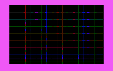
GRAPHICS PROGRAM
This BASIC program will create a series of intersecting lines using the GRAPHIC and DRAW commands to activate the high resolution areas of the screen as shown in the image below:
10 COLOR 0, 1
20 GRAPHIC 1, 1
30 FOR L = 2 TO 16
40 COLOR 1, L, 2
50 DRAW 1, 0, L * 12 TO 318, L * 12
60 DRAW 1, L * 18, 0 TO L * 18, 199
70 NEXT L
80 FOR L = 1 TO 5000 : NEXT
90 COLOR 1, 2, 3
100 GRAPHIC 0
💾 On Disk: 07 GRAPHICS
Notice that the color of lines change as they intersect other lines due to the fact that each character can only contain two colors and the black background takes one of those colors.
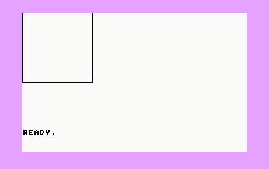
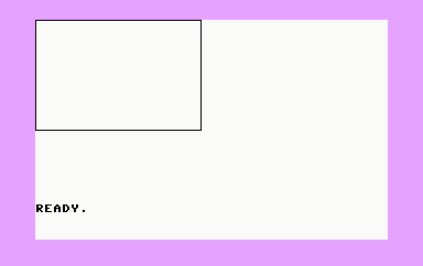
If you want to experiment with graphic commands in immediate mode, type GRAPHIC 2, 1 followed by ⏎. The screen will go blank and the READY. prompt will appear at the fourth line from the bottom of the screen as shown in the image below.
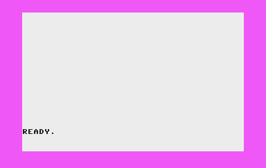
In this mode, you have the bottom five lines for commands and the top of the screen for high-res display. GRAPHIC 1, 1 will put the entire screen in high-res mode; however, you will type blindly.
You can switch between modes using GRAPHIC 0 (text) and GRAPHIC 2 (high-res). Switching does not remove what was on the previous screen unless you include ,1 at the end of the command. Below is a table that lists the various GRAPHIC command options:
| Effect | Clear |
|---|---|
| 0 Text | 0 Don’t Clear |
| 1 High-res | 1 Clear |
| 2 High-res + text | |
| 3 Multi-color | |
| 4 Multi-color + text |
TIP: The
SCNCLRcommand will clear the high-res mode.
Points, Lines, and Labels
Now the fun begins. Let’s use BASIC commands to draw shapes in high-res mode. Type GRAPHIC2,1:DRAW1,0,0 and hit ⏎. Look very closely at the top left corner of the screen. You just drew your first pixel (dot) on the Plus/4. Every line begins at the beginning.
Let’s try another one. Type DRAW1,1,1 TO 100,100 and hit ⏎. A line is drawn that connects to our dot (at coordinates X=0 and Y=0) beginning at X=1 and Y=1 to the end of the line at X=100 and Y=100. In theory (math that is) this should be a 45° line; however, because of the 8 x 8 character matrix, it’s distorted.
REMEMBER Unlike an axis in algebra or geometry, coordinates 0,0 is the upper left-hand corner, not the lower-left hand corner and positive values down and to the right.
Want to draw a line that continues from the previous? No need to remember or type the ending coordinates. Type DRAW 1 to 150,50 and hit ⏎. A new line, using absolute coordinates, will be drawn headed toward the upper right-hand corner as shown in the image below:
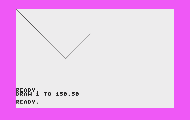
Want to complete the triangle? Type DRAW 1 TO 0,0 and hit ⏎. We will learn how we can fill in that area in the Squares, Circles, Polygons, and Painting section below.pa
Let’s break down the DRAW command syntax:
DRAW color, column, row TO column, row
Omitted everything from TO on , will draw a single dot.
There are two options for color. 0 equals the background color. 1 equals the foreground color established using the last know value or by the COLOR command.
Time for a longer example.
SINE CURVE PROGRAM
Let’s use our new found graphics commands, combined with some math (or “maths” for my European friends), to create a high-res representation of the sine function; the sine curve (or wave) as shown in the image below:
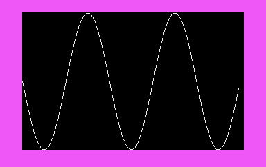
10 COLOR 0, 1
20 COLOR 1, 2
30 GRAPHIC 1, 1
40 LOCATE 0,100
50 FOR X = 1 TO 319
60 Y = INT(100+99*SIN(X/20))
70 DRAW 1 TO X, Y
80 NEXT X
90 FOR L = 1 TO 5000 : REM PAUSES SCREEN
100 NEXT L
110 GRAPHIC 0
💾 On Disk: 07 SINE WAVE
NOTE: This is the first indication of how slow 8-bit computers were when running BASIC programs. Modern computers will spit out the results of programs like this one almost immediately after hitting the
⏎key.
Without clearing the screen and immediately after running the program, replace line 70 by typing:
70 DRAW 1, X, Y
Enter RUN and the program will create the curve using points instead of lines as shown below:
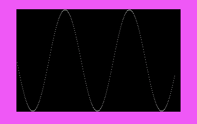
I like this version better, so keep the program in memory before continuing to the next section.
The CHAR Command
A graph alone can speak volumes; however, some graphs require characters to tell the entire story. Luckily, the Plus/4 can overlay characters on top of our graphs in high-res or multi-color graphics modes.
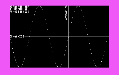
CHARACTERS ON GRAPH PROGRAM
Using the program from the previous section, add the following lines to add characters to our graph:
81 CHAR 1,0,0,"GRAPH OF" : CHAR 1,0,1,"FORMULA"
82 CHAR 1,0,2,"Y=SIN(X)"
83 DRAW 1,0,100 TO 319,100,189,0 TO 189,199
84 CHAR 1,0,12, "X-AXIS" : CHAR 1,22,0,"Y"
85 CHAR 1,22,2,"A" : CHAR 1,22,3,"X"
86 CHAR 1,22,4,"T" : CHAR 1,22,5,"S"
The result is a graphic with character labels as shown in the image below:
Squares, Circles, Polygons, and Painting
Not only does Commodore BASIC 3.5 provide commands to draw single pixels and lines, it also provides the BOX, CIRCLE, and PAINT commands. These commands expedite the creation of on-screen graphics.
Drawing Rectangles
Use the BOX command to create rectangles using two coordinates that describe the opposite corners of the box.
SQUARE PROGRAM
Below is a sample BOX command and an image of the results:
10 GRAPHIC 2,1
20 BOX 1,0,0,100,100
💾 On Disk: 07 SQUARE
Line 10 switches to high-res graphics mode with a command text below, 2, and clears the screen, 1.
The first value in line 20, 1, is the value to draw, rather than erase which is 0. The next two coordinates, 0,0, are the upper-left coordinates (can be anywhere on the screen) and the next two numbers,100,100, are the lower-left coordinates. Since both numbers are 100, this command will draw a square. Values of 150,100 will draw a rectangle as shown below:
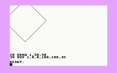
ROTATE SQUARE PROGRAM
Let’s add a new line 20 and copy line 20 to line 30 while adding an additional attribute to the `BOX command; a rotation.
10 GRAPHIC 2,1
20 DRAW 1,50,50 : REM ROTATION POINT
30 BOX 1,0,0,100,100,45
💾 On Disk: 07 ROTATE SQUARE
Line 20 draws the center of our rotation point. The value 45 will rotate the box 45° clockwise at the center point of the polygon drawn as a single point on the screen. The results are shown below:
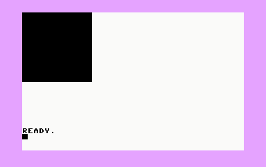
FILL RECTANG PROGRAM
Much code and “ciphering” is necessary if you want to fill polygons using the DRAW command. Luckily, another attribute for the BOX command provides the ability to fill polygons as shown in the code and image below:
10 GRAPHIC 2,1
20 BOX 1,0,0,100,100,,1
💾 On Disk: 07 FILL RECTANG
NOTE: Line 30 omits a rotation attribute and the
1instructs the command to fill the polygon.
Let’s use the commands we’ve learned in more complete programs.
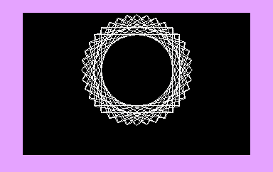
SPIROGRAPH^® PROGRAM
This first program that draws multiple boxes from the same center point at random rotations. The result is a computerized and old school Spirograph.
10 COLOR 0,1
20 COLOR 1,2
30 GRAPHIC 2,1
40 A = RND(1) * 20 + 10
50 FOR L = 0 TO 359 STEP A
60 BOX 1,100,30,220,130,L
70 NEXT L
80 FOR L = 1 TO 2000 : NEXT L
90 GRAPHIC 0,1
💾 On Disk: 07 SPIROGRAPH
MODERN ART PROGRAM
Time to create modern art; a bunch of colorful rectangles drawn on the screen over and over. Yes, some people consider this art. Type in or load the program below:
5 TRAP 60 : REM RESETS SCREEN ON ERROR
10 GRAPHIC 2,1
20 DEF FNA(X) = INT(RND(1)*X)
30 COLOR 1, FNA(15)+1
40 BOX 1,FNA(320),FNA(160),FNA(320),FNA(160),,1
50 GOTO 30
60 COLOR 1,2,3 : GRAPHIC 0
💾 On Disk: 07 MODERN ART
As this codes runs, notice as the rectangles begin to overlap each other, the color of the previous rectangle is affected and overwritten several pixels in front of the new area drawn. This is a limitation of the graphic mode used. It only supports two colors per 8 x 8 area. In the Drawing Circles section, we’ll use multi-color mode to overcome this limitation.
NOTE: We have a new BASIC command in line
10.TRAPintercepts errors in programming conditions. It then writes the line number where the error occurred to variableEL(error line). A programmer can redirect their programming code to a specific line after the error. Think of it as aGOTOfor errors. In this example, theTRAPcommand creatively exits graphics mode. When the user hits the R/S key, an error is produced. Without theTRAPcommand, the program would simply stop and freeze on the graphics screen. The user then types aGRAPHICcommand blindly to get back to a text screen. Instead, the program exits the graphics screen gracefully to a text screen with a soft color palette to a R/S key press has occurred.
Drawing Circles
Let’s use the CIRCLE command to draw two circles as shown in the image below.
10 GRAPHICS 2,1
20 CIRCLE 1,50,50,25,25
30 CIRCLE 1,150,50,25,20
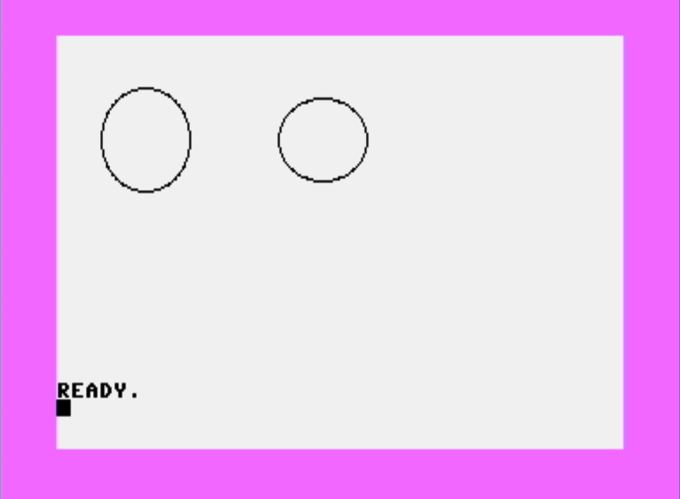
The program above includes two CIRCLE commands in lines 20 and 30. Line 20 draws (1) a circle starting at a center point (50,50) out to a radius of defined by two coordinates (25,25); however, if you look at the output on my NTSC screen, while the math describes a perfect circle, the Plus/4 displays an ellipse. That’s because pixels on an NTSC Plus/4, are not square but rectangular as shown in the image below:
The second line accounts for this to give a more visually accurate rendering of a circle.
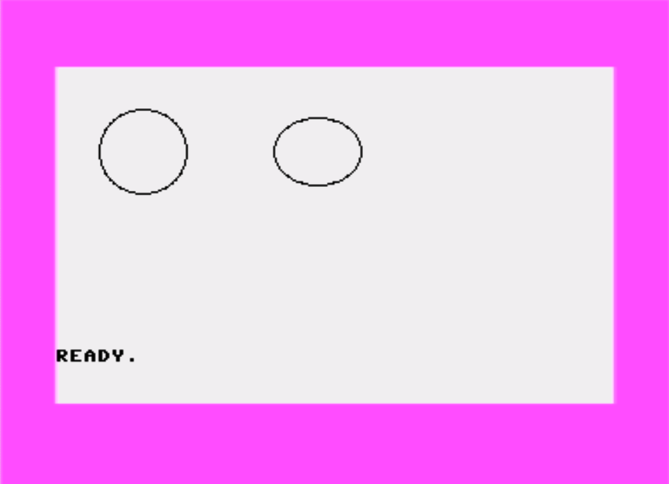
My fellow Commodore Plus/4 users over the pond using PAL monitors will not see this distortion, as shown below:
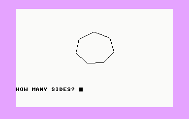
SHAPES PROGRAM
The CIRCLE command can draw shapes in addition to circles as the code below demonstrates. Line 35 is not included in the user’s manual code. This line erases the previous shape before a new one is drawn. I found this preferred over the manual’s drawing shapes over the top of each other.
10 GRAPHIC 2,1
20 INPUT "HOW MANY SIDES";A
30 IF A < 2 OR A > 100 THEN ? "DON'T BE RIDICULOUS" : GOTO 20
35 SCNCLR : REM MY ADDITION
40 CIRCLE 1,160,80,40,33,,,,360/A
50 GOTO 20
💾 On Disk: 07 SHAPES
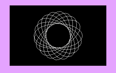
An earlier program simulated a Spirograph. Let’s swap out the Spirograph ring insert and create another shape.
10 COLOR 0,1
20 COLOR 1,2
30 GRAPHIC 1,1
40 A = RND(1) * 20 + 10
50 FOR L = 0 TO 359 STEP A
60 CIRCLE 1, 160, 100, 80, 40,,,L
70 NEXT L
80 FOR L = 1 TO 2000 : NEXT L
90 GRAPHIC 0,1
💾 On Disk: 07 SPIROGRAPH 2
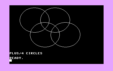
The program below will draw four circles. It’s a simple program that uses math and some variables to space the circles out.
10 COLOR 0,1
20 COLOR 1,2
30 GRAPHIC 2,1
40 FOR L = 1 TO 4 : REM CHANGE `4` to `5`
50 Y = 50
60 IF L = 2 OR L = 4 THEN Y = 100
70 X = L * 35 + 50
80 CIRCLE 1,X,Y,50,42
90 NEXT L
100 ? "PLUS/4 CIRCLES"
💾 On Disk: 07 CIRCLES
The PAINT Command
Let’s fill in portions of the overlapping circles. Add the lines below to the previous program.
110 FOR L = 0 TO 2
120 PAINT 1,120 + 35 * L,75
130 NEXT L
💾 On Disk: 07 VENN
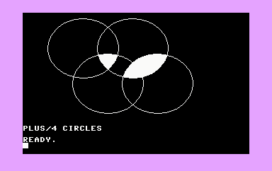
While not a true Venn diagram, we could use the code to create the circles and area fills that become the makings of a BASIC Venn diagram program.
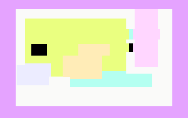
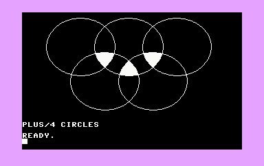
NOTE: In the video, I demonstrate what I believe was the original intent of the previous two programs, the creation of the Olympic symbol. I add the fifth circle and when complete, both examples make more sense as shown in the image below:
Multi-Color Graphics
The two programs below demonstrate the Plus/4’s multi-color graphics mode.
MULTI-COLOR PROGRAM
10 COLOR 0,1
20 GRAPHIC 4,1
30 FOR L = 1 TO 5
40 Q = L : IF Q > 3 THEN Q = Q - 3
50 COLOR Q,L+1,0 : REM ADDED LUM VALUE
60 Y = 50
70 IF L = 2 OR L = 4 THEN Y = 100
80 X = L * 18 + 25
90 CIRCLE Q,X,Y,25,42
100 NEXT L
110 COLOR 1,2 : REM ADDED FOR LEGIBILITY
💾 On Disk: 07 MULTI-COLOR
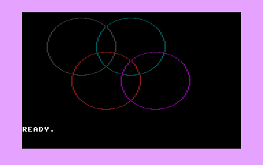
NOTE: Like the previous two programs, the modification of this program to draw five circles is a better example. Can you figure out how to modify the program to include the fifth circle?
NEON SIGN PROGRAM
The last program in this chapter create an 8-bit simulation of a flashing neon sign. What’s the message you ask? You’ll have to type in the code to find out, or better yet, review the code and try to anticipate the message.
10 COLOR 0,1
20 GRAPHIC 3,1
30 COLOR 3,1
40 TRAP 200
50 DRAW 3,10,10 TO 10,100 : DRAW 3,10,55 TO 30,55
60 DRAW 3,30,10 TO 30,100 : DRAW 3,50,10 TO 80,10
70 DRAW 3,65,10 TO 65,100 : DRAW 3,50,100 TO 80,100
80 FOR L = 0 TO 7
90 COLOR 3,2,L : REM CHANGE 2 TO 9 (ORANGE) FOR MORE FUN
100 FOR M = 1 TO 100 : NEXT M
110 NEXT L
120 COLOR 3,1
130 FOR M = 1 TO 100 : NEXT M
140 GOTO 80
200 GRAPHIC 0 : COLOR 1,2,7
💾 On Disk: 07 NEON SIGN
I don’t include an image for this one because I don’t want to spoil the 8-bit neon light simulating surprise. In the companion video I also share how to make the neon sign seem more, “neony!”
Final Thoughts
This chapter was a blast; however, it did take a long time to prepare this post and the video.
In the next chapter, we will use the Plus/4 to play sounds and music. Add these concepts to this chapter and we are on our way to creating games and audio/visual demos in Commodore BASIC 3.5.
You won’t want to miss that fun. Make sure you SUBSCRIBE to my YouTube channel.
Join the Fun
Help make this series better! Post feedback, questions, and ideas. Let me know if you are following along. Let’s make this a community project. For now, Leave your comments and thoughts below or in the comments under the YouTube video.
Thanks for watching and if you are inclined, please let other Commodore fans know about the series, my blog, and the YouTube channel, by sharing these videos using #retroCombs.
🕹️ retroCombs, OUT!